As the Team Captain and Executive Lead of the Lancer Aero Design club, I am responsible for guiding our team through the design and manufacturing of a RC aircraft for the 2025 SAE Aero Design competition. This competition challenges us to apply aerospace engineering principles to a real-world design problem, testing our skills in aircraft design, fabrication, and mission execution. It's an incredible opportunity to lead a dedicated team and bring our engineering ideas to life in a competitive setting.
The Lancer Aero Design club enrolled in the Regular Class competition, where the objective is to design and build an all-electric radio-controlled aircraft, optimized for payload capacity. Regular class has many different design requirements including the following: maximum aircraft gross takeoff weight is 55 lbs; the design must also incorporate the thought of ease of assembly and disassembly as the largest single component must measure 48 inches or less along any primary axis, also, several constraints were placed on material and equipment such as no fiber reinforced plastic, no stability assistance and aircraft must also be propelled by a single electric motor not exceeding 750 Watts . During the design process, the team analyzed the regular class scoring requirement to optimize the plane design. To achieve the highest final score, the team chose the longest allowable wingspan and 6.5 aspect ratio .
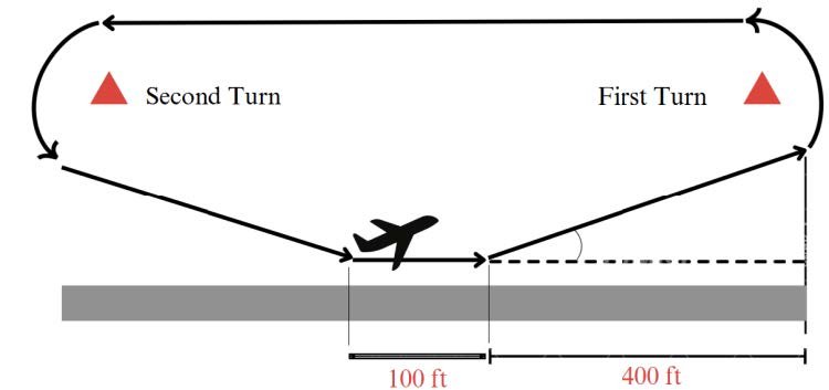
The goal of this project is to build a radio-controlled aircraft that can carry the heaviest possible payload while staying under 55 lbs maximum takeoff weight. The plane must complete an estimated 1,000-foot mission, including a maximum 100-foot runway for takeoff and 100-foot landing, and 800 feet of flight (Figure 2). During flight, the first turn can only happen 400 feet after takeoff. There is no time limit in the air, so as long as the plane safely covers the required distance, it will earn points. The main objective is to score as many points as possible, which translate to carrying the maximum possible payload and maximizing the wingspan.
In addition to the competition's general performance requirements, successfully completing the event also depends on meeting three key criteria which are dimensional requirements, material requirements, and payload requirements.
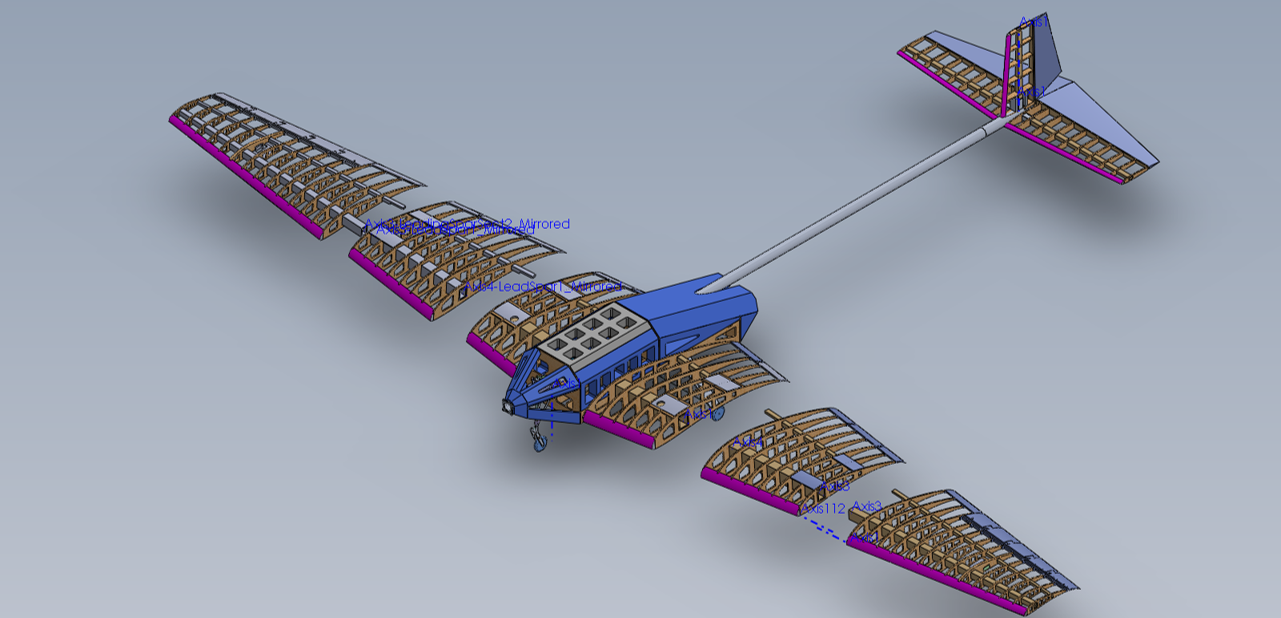
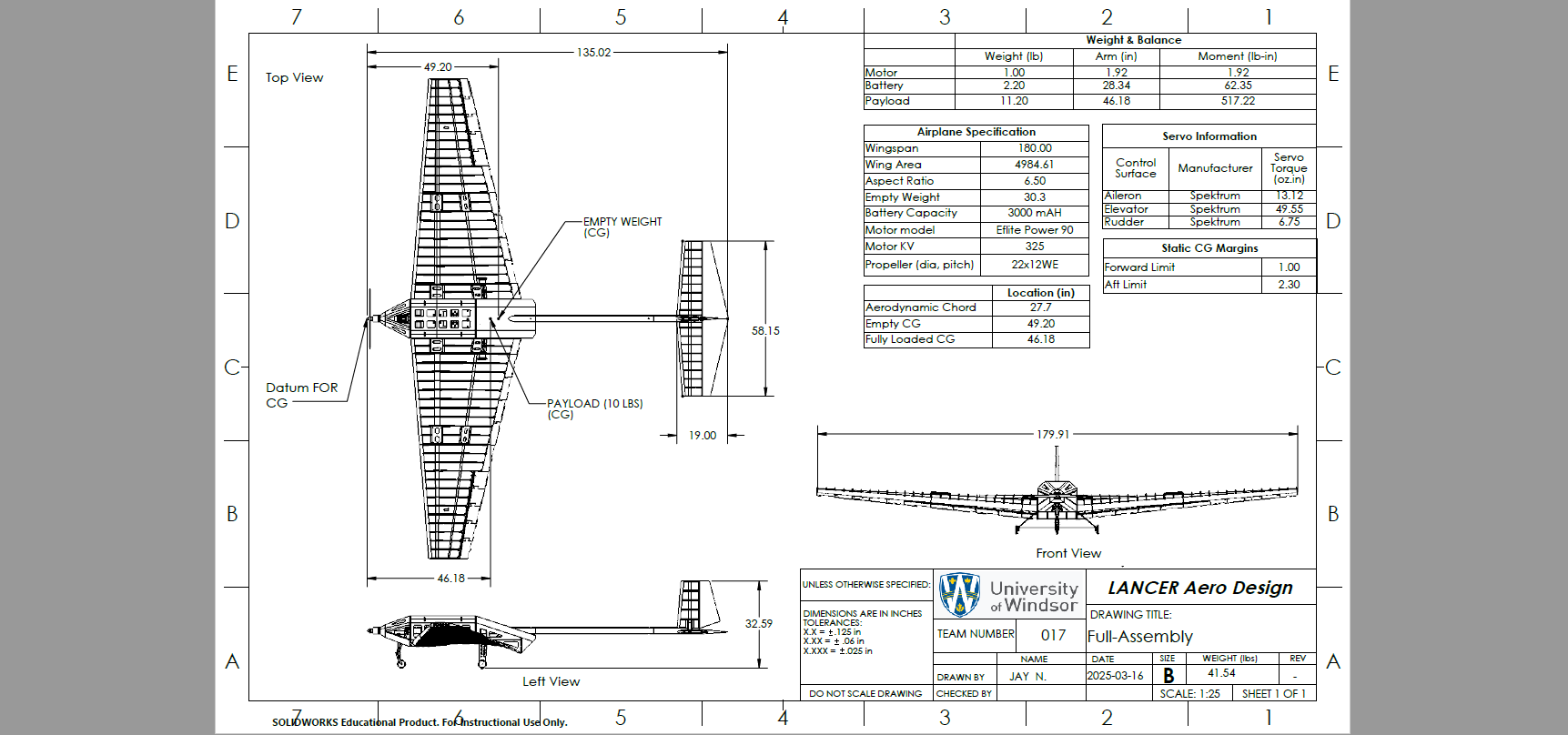
(Picture 1) This is a full-assembly drawing of an RC aircraft designed by the University of Windsor's Lancer Aero Design team. The drawing highlights key aircraft dimensions and specifications. The overall wingspan of the aircraft is 180 inches, with a total length of approximately 58.15 inches and a height of 32.59 inches. The top, front, and side views show the layout of major components including payload placement, CG locations, and structural details. Additional tables provide information on weight and balance, servo specifications, and CG margins, ensuring proper flight performance and stability.
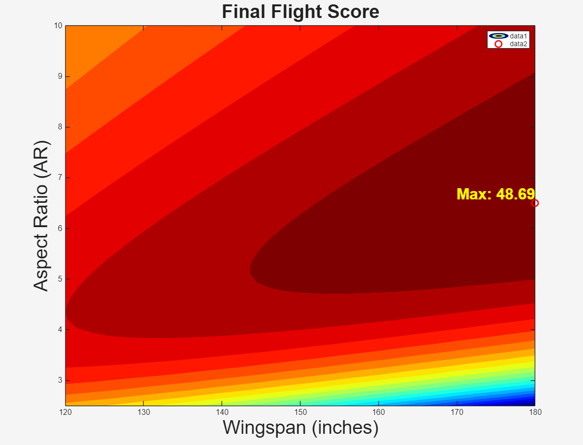
(Picture 2) The team determined the optimal wing size by selecting the configuration that yielded the highest Final Flight Score (FFS), recognizing the wing as the centerpiece around which the rest of the aircraft is designed. Key factors influencing FFS were payload capacity—calculated as total weight minus empty weight—and the structural and aerodynamic implications of various wing geometries. By analyzing 4,637 configurations using a contour graph, the team found that the top-performing designs all used the maximum allowed wingspan of 180 inches, primarily to take advantage of bonus points. While configurations with slightly shorter wingspans and higher aspect ratios offered comparable performance, structural limitations and the requirement for 48-inch assembly sections made these less practical. Ultimately, the team selected a wingspan of 180 inches with an aspect ratio of 6.5, achieving the highest FFS of approximately 48.68 points.
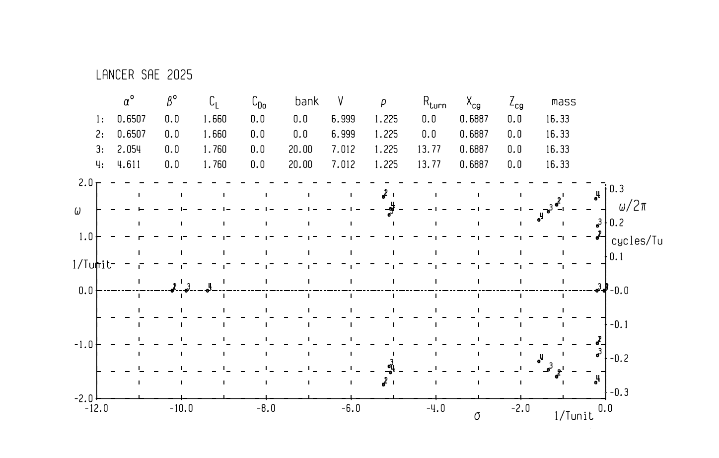
(Picture 3) The aircraft’s stability was assessed through both static and dynamic analyses, using AVL stability derivatives and eigenvalue calculations. Static stability was confirmed by meeting two essential conditions: a pitching moment coefficient (CM) of zero and a negative pitching moment slope (CMα = -0.639), both derived from four AVL run cases. For dynamic stability, eigenvalue plots were used, where the real part (σ) of each eigenvalue determines stability—negative values indicate stable behavior. Across all run cases, including the worst-case scenario with the highest forces, σ remained negative, confirming that the aircraft remains dynamically stable even under adverse conditions.
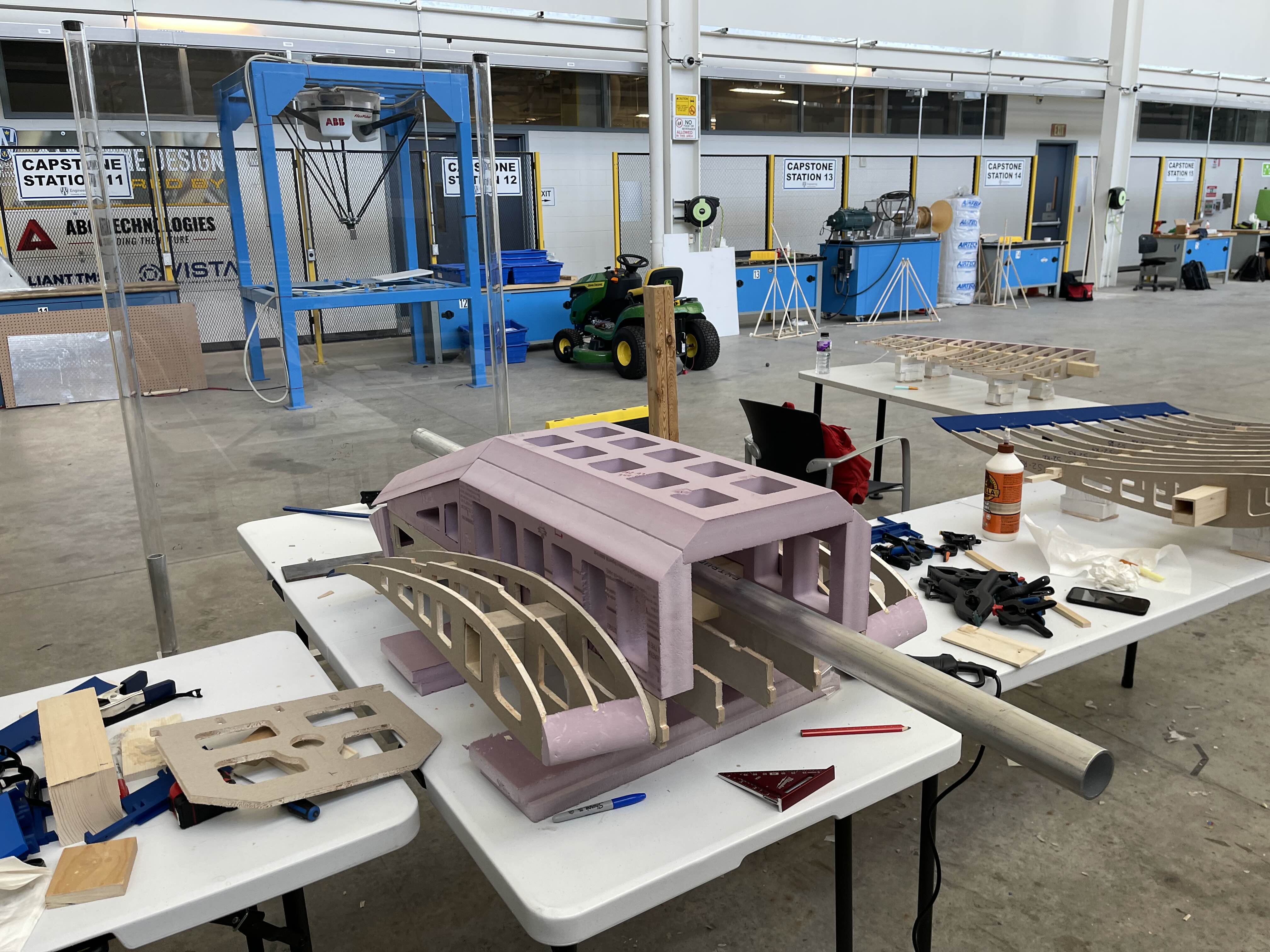
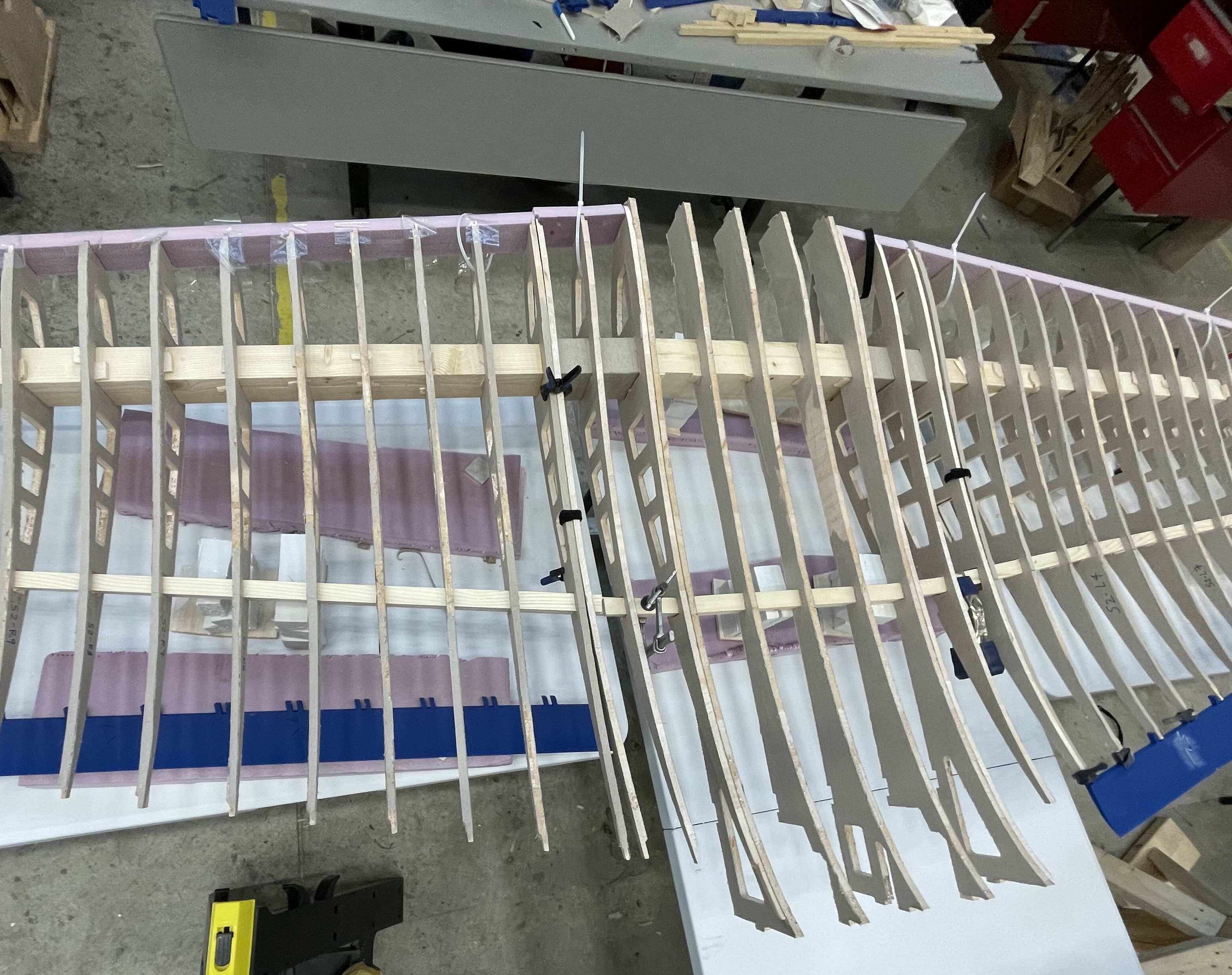
During the manufacturing phase of the RC SAE airplane project, I led a construction of a lightweight yet structurally RC aircraft by strategically selecting and utilizing materials. The majority of the airplane’s internal structure, especially the airfoil ribs, was crafted using balsa wood due to its excellent strength-to-weight ratio. For the fuselage and wing cores, we used XPS foam, which allowed us to maintain rigidity while minimizing overall weight—crucial for performance and payload efficiency.
The tail assembly was designed using 6061 aluminum tubing with 0.045 in wall thickness , chosen for its durability, machinability, stock available. To accomodate the 48-inch modularity requirement, we implemented a tube-in-tube connection method that enabled the tail to be disassembled and reattached with ease. This design decision greatly improved transportation and storage flexibility while maintaining structural integrity. The propulsion system featured a 1200 W Spektrum motor, paired with a power limiter to comply with SAE competition requirements.
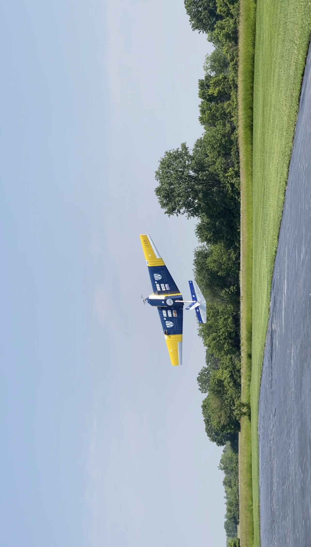
One of the most significant accomplishments was the timeline: our team fully manufactured, constructed and assembled the entire aircraft in just 1 month , something no prior team had managed to achieve. This rapid turnaround showcased our efficient coordination, planning, and dedication throughout the manufacturing process.